Sluice board position indicators:
When in use current position of the closing boards is visible even when the board cannot be seen. You will always know whether the gate is closed or open. In the case of weir gates they help adjusting and reading the overflow level in a simple way.
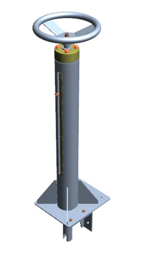 Analogue board position indicator
1.) Analogue board position indicator installed on the operating platform:
During the movement of the board a pointer moves in the slot of the operating platform parallel to the board so that the current position of the board can be read. The bronze nut installed inside the lifting tube on the top of the board is located inside the operating platform. The socket-head bolt fixed in its side indicates the position of the board in the slot of the standpipe. The position of the board can be read on the scale glued to the standpipe. Due to the height of the operating platform only ranges less than 600 mm can be indicated.
Downloadable material:
| Analogue board position indicator 3D |
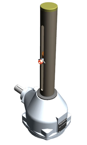 Analogue board position indicator installed of the drive gear
2.) Analogue board position indicator installed on the top of the drive gear:
During the movement of the board a pointer moves in the slot of the tube mounted on the top of the drive gear proportionally to the board, thus allowing you to read the position of the board. A bronze nut moving upwards or downwards according to the sense of rotation is mounted on the fine threaded screw spindle rotating together with the acme threaded lifting spindle. A screw fixing the pointer secures it against rotation. The position of the sluice board can be seen on the scale glued to the pipe and calibrated according to the ratio of the thread pitches of the two spindles.
Downloadable material:
| Analogue board position indicator installed of the drive gear 3D |
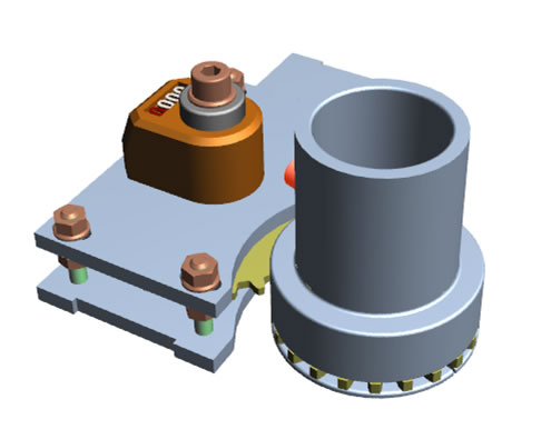 Digital board position display
3.) Digital board position display:
This compact board position display can be installed anywhere on the gate operating gear; on the top of the drive gear in a protecting enclosure, inside the lifting beam or also on the lifting platform. The gear wheels modified by the ratio conforming to the pitch of the acme threaded lifting spindle drive a 5 digit counter device. The movement of the sluice board is displayed in mm by the fifth digit (RED NUMERAL) and in cm by the black numerals. The numerals increase when the board ascends: the counter shows then the dimension of the gap below the board or the top edge of the board in the case of a weir gate.
Downloadable material:
| Digital board position display 3D |
Blocking of the sluice gate:
This device provides for the protection against any unauthorized operation or maladjustment of sluice gates installed in public areas, in inland water channels, irrigation canals or at flood-control works.
After the removal of the operating handwheel or crank handle the lock plate placed on the square end of the lifting spindle slides onto the lock tab, and by installing a padlock, the drive can be blocked, the spindle cannot be rotated.
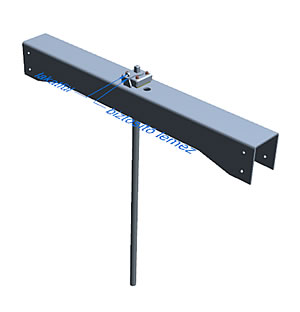 Blocking of the AZ sluice gate
Downloadable material:
| Blocking of the AZ sluice gate 3D |
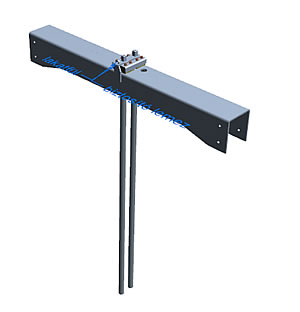 Blocking of the BZ sluice gate
Downloadable material:
| Blocking of the BZ sluice gate 3D |


